

Isolate the Power Line Carrier terminal (DPLC) from the High Voltage the Power line Carrie Terminal
Establish the impedance coupling of the line with the impedance of the DPLC
Filter or reject the Radio Frequency – RF (20-500 kHz) of the DPLC and/or the low frequency of the Electrical energy (50/60 Hz)


PLC 9550
The 9550 Line Trap features low loss and modular design. PLC is able to design line traps according to customer requirements given the various application parameters such as outline dimensions and short time current per IEC Series 2 standards.
The PLC 9550 Line Trap is inserted in series with high voltage a.c. power transmission lines to prevent loss of carrier-frequency signal power in the range of 30 to 500 kHz. It also minimizes interference from carrier signaling systems on adjacent power transmission lines.

PLC 9510 P
The PLC 9510 line tuner matches the impedance of the power line carrier (PLC) terminal to that of the high voltage power line in order to reduce the insertion loss for the transmission of PLC signals over the power line. In addition, isolation from the power frequency voltage and transient over voltages is provided.
This line tuner can be used with PLC communication systems connected to coupling capacitors having a capacitance between 1,400 and 25,000 pF.
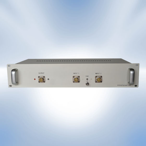

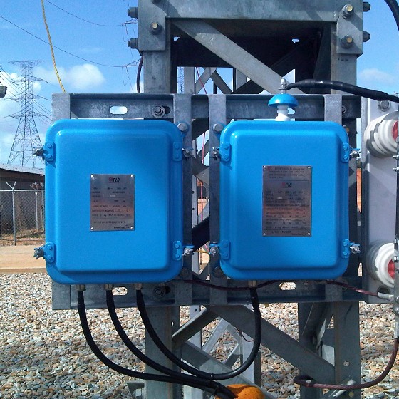
Balance Transformer
The Balance Transformer provides isolation between two Power Line Carrier Equipment over a single coaxial output, providing isolation between them and avoid interference. Allows each output line to be balanced with its associated Line Tuning Equipment.
PLC 9550
The 9550 Line Trap features low loss and modular design. PLC is able to design line traps according to customer requirements given the various application parameters such as outline dimensions and short time current per IEC Series 2 standards.
The PLC 9550 Line Trap is inserted in series with high voltage a.c. power transmission lines to prevent loss of carrier-frequency signal power in the range of 30 to 500 kHz. It also minimizes interference from carrier signaling systems on adjacent power transmission lines.
PLC 9510 P
The PLC 9510 line tuner matches the impedance of the power line carrier (PLC) terminal to that of the high voltage power line in order to reduce the insertion loss for the transmission of PLC signals over the power line. In addition, isolation from the power frequency voltage and transient over voltages is provided.
This line tuner can be used with PLC communication systems connected to coupling capacitors having a capacitance between 1,400 and 25,000 pF.
Balance Transformer
The Balance Transformer provides isolation between two Power Line Carrier Equipment over a single coaxial output, providing isolation between them and avoid interference. Allows each output line to be balanced with its associated Line Tuning Equipment.